
Figure 1. Single zone grid used in the transonic diffuser computation
1. Conceptual Modeling
2. Mathematical Modeling
3. Programming Activities
4. Discreatization
and Algorithm Selection
5. Numerical Solution
6. Solution Presentation
Hongman's work included
errors associated with phases 4 and 5. For the current study, we may consider
the same phases and maybe phase 2 for the investigation of the CFD simulation
errors . (Or we can choose one specific phase)
2. Simulation Parameters:
a. Parameters associated with the program: This may include the modeling of the viscous terms (Thin-Layer N-S, Full N-S, or Euler for no viscous terms), inviscid flux schemes (Roe, Van-Leer, AUSM+), limiters, turbulence models (k-w, k-epsilon, Spalart-Allmaras). The number of cycles for the convergence of the solution is influenced by these parameters.
b. Parameters used in the description of the geometry
c. Parameters associated with the grid (discreatization of the flow field): These will effect the discreatization error.
d. Flow parameters: Mach number M, Reynolds number Re , and other flow conditions.
(b) and (c) are used in the description of the boundary
conditions.
3. Review of the Validation Cases for GASP version 4:
All the validation cases except the last two ( turbulent wake of a flat plate and mixing-layer problem) are taken from NPARC alliance validation archive. The grid files and the experimental results of these cases are given in the same location.
3.1. Blasius Flat Plate:
Problem
Description: 2-D, steady, laminar, uniform flow on a flat plate. The
Blasius similarity solution is the exact solution to this problem.
Flow Parameters: M, Re, static temperature T, density rho, velocity v, and static pressure p of the inflow (freestream conditions)
Grid: 2-D, single zone grid (21x41x2)
Flow Parameters: M, Re, static temperature T, density rho, velocity v, and static pressure p of the inflow (freestream conditions)
Grid: 2-D, single zone grid (21x41x2)
Flow Parameters: P0 (total pressure at the inlet), T0 (total temperature at the inlet), M0 (inlet Mach number), Pb (back pressure).
Grid: 2-D, single zone grid
(81 x 51 x 2)
Figure 1. Single zone grid used in the transonic diffuser
computation
Flow Parameters: Freestream M, T, rho and Re, angle of attack.
Grid: 2-D, single zone C-grid (369 x 65 x 2)
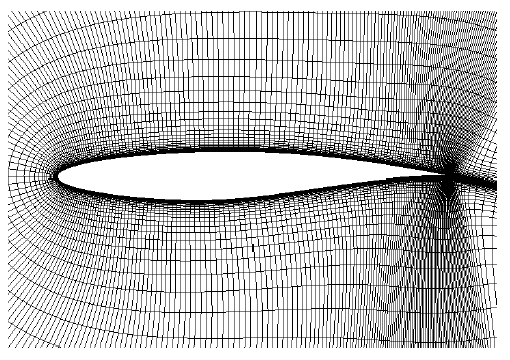
Figure 2. Close-up view of the RAE 2822 airfoil grid
Flow Parameters: Vi (inlet velocity), T, rho, Re (based on unit length) and Re_h (based on step height)
Parameters Defining the Geometry: lu ( length in the freestream direction upstream of the step), ld (length in the freestream direction downstream of the step), h step height
Grid: 2-D, two zone grid. 1st
zone upstream of the step (51 x 66 x 2)
2nd zone downstream of the step (138 x 93 x 2)

Figure 3. Close-up view of the grid in the step region
Flow Parameters: The freestream M, T, rho and Re (based on unit length)
Grid: 2-D, two zone grid. 1st
zone models the flat plate (51 x 151 x 2)
2nd zone models the wake region (71 x 151 x 2)
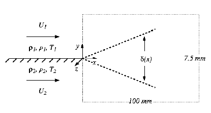
In the validation, two cases were studied: Compressible shear layer involving supersonic flow and incompressible mixing layer.
Flow Parameters: For the compressible
case: The freestream conditions of the stream 2 (U2, T, rho, and AoA) are
held constant. U1 is changed for obtaining different convection Mach number
Mc=(U1-U2)/(a1-a2). The rest of the flow conditions of stream 2 are held
constant.
For the incompressible case: T and rho for both streams are held constant.
U1 and U2 are different.
Grid: 2-D, single zone grid.
For the compressible case: (201 x 52 x 2)
For the incompressible case: (201 x 101 x 2)

Figure 5. The grid used in the compressible shear layer computations
Table 1. Total number of grid points for each validation case:
|
|
|
|
|
|
|
|
|
|
|
|
|
|
|
|
|
|
|
|
|
|
|
|
|
|
|